|
||||||||||||||||||||||||||||||||||||||||||||||||||||||||||||||||||||||||||||
The LPF UnitLPF Unit contains transmitter low pass filters, antenna switch, SWR meter and associated control circuits. Let's look closely at them... The Low Pass FiltersThe low pass filters are used to filter transmitter harmonics down to acceptable level. NEON uses five filters. All filters are Cauer type 2nd order for 160m/80m and 3rd order for the other bands. The 40m and 30m shares one filter, as well as 20m/17m and 15m/12m/10m. So there are 5 filters. The filters inductors are wound on T80 cores, -2 material is used for 160m/80m, -6 material is used for 40/30m and -17 one for 20m and higher. Each filter's capacitor consists of several high quality high voltage NP0 1206 ceramic capacitors in parallel. Table 1. LPF stopband attenuation
The Antenna SwitchOne of the NEON design goals was basic SO2R operation "in a single box". I decided that matrix antenna switch is exactly what I need for such use. Also having a flexible antenna switching system in transceiver should help with more complicated configurations (for high power operation, with many antennas and etc.). The antenna switch can connect any of the three antennas to any of the two RX inputs and one TX output. Also it incoorporates power splitter (which is used when both RX share one antenna) and provides TX/RX switching. Used relays configuration ensures that RX input(s) will never be connected to TX output, even if something bad will happen with the firmware/control circuits/relays. Basic switch operation should be clear from its schematics. If both receivers use the same antenna and both are receiving, the signal from the RX A relay path is divided for RX A/RX B by the Minicircuits power splitter U5 (ADP-2-1W+). One of the important parameter of such switch is the isolation of the different signal paths. Consider 50W TX power (+47dBm), signal at MDS level (-138dBm with 500Hz bandwidth) and broadband TX noise at -150dBc/Hz for the in band SO2R and -160dBc/Hz for the neighbor band, we will need >62dB / >52dB isolation for interference free operation. In a real life the isolation can be a bit worser. You can view the measurement results in the tables below. The following two tables shows TX to RX path isolation in a different configurations. The RX B antenna selection had neglible effect to RX A/TX isolation, the same is true for RX A antenna selection and RX B/TX isolation. There are three numbers for each configuration - 160m isolation, 40m isolation and 10m one. The bold numbers are for the worst isolation. Table 2. TX path to RX A path feedthrough, dB (160m / 40m / 10m)
Table 3. TX path to RX B path feedthrough
As you can see from the measurements the switch provides the necessary isolation (with some margin) for the classical SO2R operation (when you transmit and receive simultaneously on a different bands) and in band SO2R for the bands below 20m. But in real use (not at the lab table) the 10m isolation (more than 52dB) should not introduce any problem too. You can also see that switch provides a good protection for the very bad case if something bad happened with switch control logic (the transmitted signal will be attenuated at least by 50dB at the receiver input). Another important parameter is RX A / RX B isolation. You may need a good isolation here if you are using diversity reception and use antennas with a very different gain (for example full size vertical on RX A and small flag on RX B). The RX A/RX B isolation measurements results are shown in the following table. Table 4. RX A / RX B isolation
The worst case isolation is 58dB on 10m, 70dB on 40m and a very respectable 83dB on topband. It should be more than enough. Now some words about relays. I used old Soviet Union relays for the switch - the fast reed relays for RX paths and hermetic sealed ones for the TX path. These relays have contacts with special coating, so they can reliable switch low voltage/currents without distortions/losses. Many modern relays should be suitable for the switch, but they may require DC wetting of the contacts. SWR meter and controlThe LPF Unit also contains SWR meter and control circuits for the LPF switching, fan control and antenna switch control. As the other NEON's units LPF Unit is controller via the SPI bus.
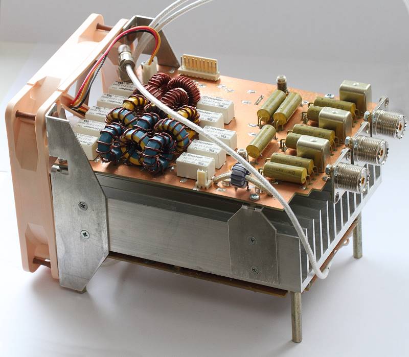
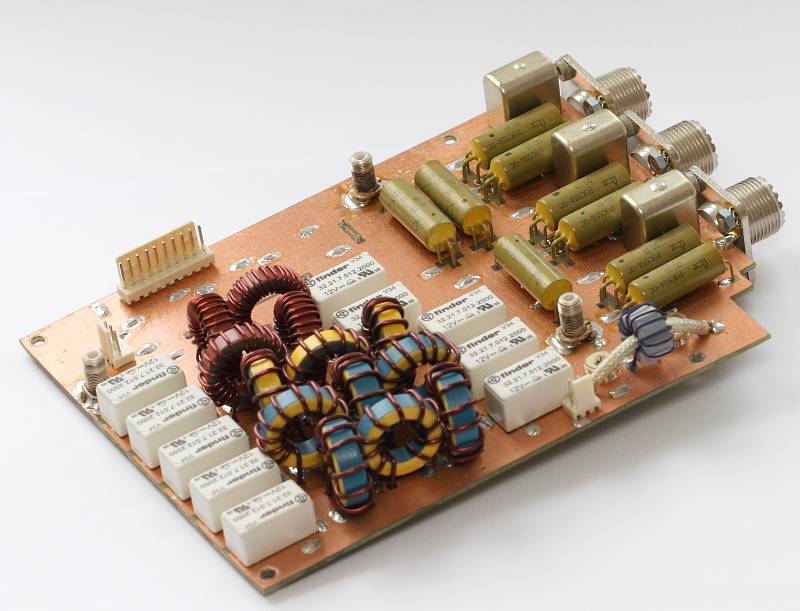
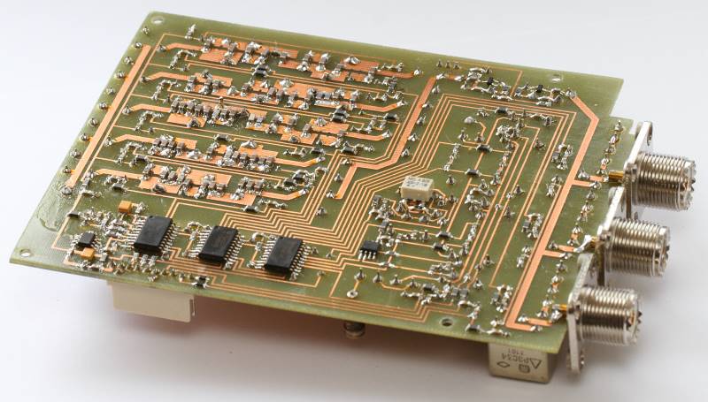
The LPF Unit schematics can be downloaded Here are the photos of the LPF Unit. The LPF unit is mounted on the back of the PA heatsink. The quiet 120mm PA cooling fan also provides cooling for the LPF inductors.
|

All materials provided here are copyright by Oleg Skydan UR3IQO (unless otherwise explicitely specified). In all cases, materials are
provided for the purpose of self education
and training in Amateur Radio. No use may be made for commercial purposes without
permission of the author.
Please send any comments and questions to Oleg Skydan UR3IQO.
This page was last updated on 10.09.2020 06:50