|
||||||||||||||||||||||||||||||||||||||||||||||||||||||||||||||||||||||||||||||||||||||||||||||||||||
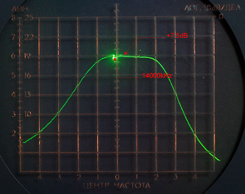
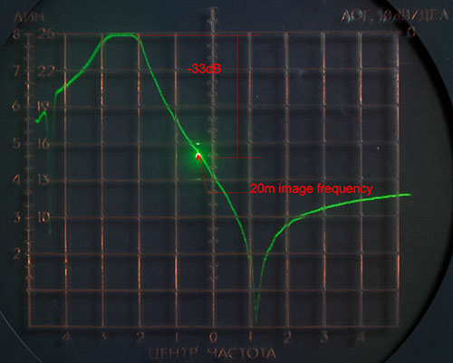
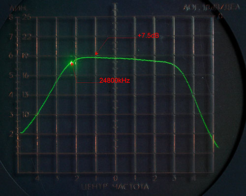
The RF UnitThe most important components of the RF Unit are Preamplifier, Mixer and Roofing filters. Let's look closely at them... The PreamplifierThe main goal was to build a low noise preamplifier (NF<2..3dB) with high IP3o (IP3o>+43dBm) and 12...16dB gain. The IP3 performance of the frontend with such preamplifier in line will be determined solely by the mixer's IP3 and the NF of the transceiver will be around 6dB... Designing a preamplifier for the high IP3i mixer (in +40dBm range) is not a trivial task. I have made a lot of experiments with different devices (including MMICs like SGA7489, U310 JFETs and even some medium power Russian JFETs). The excellent IP3 performance (IP3o=+44dBm), good stability and NF were obtained with the Norton amplifier using BFG591 transistor (actually only this preamplifier had the required IP3o performance). The only drawback was low gain - this preamplifier showed only 8.5dB of gain. After some exercises with the Excel spreadsheet (used for level/NF diagramm calculation) it appeared that I will have the NF=9...10dB for the complete transceiver in the worst case (with the lossy BPF on 10m). I decided it is fairly good number to stop searching for the better preamplifier. The preamplifier BPFsWith the downconversion IF architecture the BPF should be installed after the preamplifier (to cut the excessive noise in the image passband and not degrade preamplifier NF performance). The stopband performance is not an issue here - -20dB is more than enough. I never use the preamplifier below 14MHz, so the preamplifier operates only on 14MHz and higher. Another trick to simplify the output BPFs is to combine 17m/15m and 12m/10m filters. So only 3 BPFs are needed. The BPFs' coils are wound on the T50-6 powder iron cores. The nonlinearity of the cores is not an issure here - filters are wide enough (low Q) and -6 material behaves well on higher bands (the measured IP3i was better +45dBm). 20m BPFTwo stage BPF is sufficient for the 20m band. The passband and stopband characteristics are shown below. The IL is approx. 1dB.
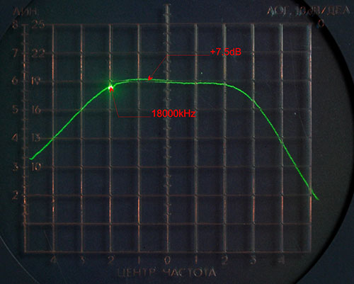
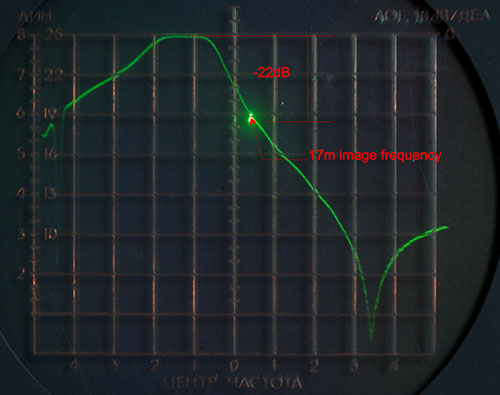
17/15m BPFTwo stage BPF is sufficient to cover 17m and 15m. The passband and stopband characteristics are shown below. The IL is approx. 1dB.
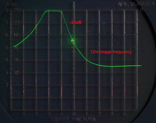
12/10m BPFThree stage BPF is used to cover 12m and 10m bands. The passband and stopband characteristics are shown below. The IL is approx. 1dB.
The MixerThe mixer uses a novel architecture
utilizing TL transformers and fast bus switches. You can find more information in my QEX article
You can view the measurements results in the tables below. Table 1. True TLT mixer conversion loss
Table 2. True TLT mixer IP3 performance
The Roofing FiltersThe roofing filters are needed to reject the second conversion image channel (the second conversion image will be attenuated additionally because of the image rejection second mixer architecture) and attenuate close strong signals. There are two roofing filters - one with 2.8kHz bandwidth (4 poles) and one with the 0.5kHz bandwidth (3 poles). Both roofing filters are made using ladder crystal filters. Such filters are easy to design and build. I used the high quality military grade crystals (the large old crystals made in the USSR). The manufacturer claimed Q>500,000. Good crystals are important to obtain required linearity and low in-band losses. As can bee seen from the measurements below the filters are really low loss with the excellent linearity. 2800Hz Roofing filterTable 3. Wide roofing filter performance
+ - at the second conversion image frequency (approx. 40kHz up) Table 4. Wide roofing filter IP3 performance
600Hz Roofing filterTable 5. Narrow roofing filter performance
+ - at the second conversion image frequency (approx. 40kHz up) Table 4. Narrow roofing filter IP3 performance
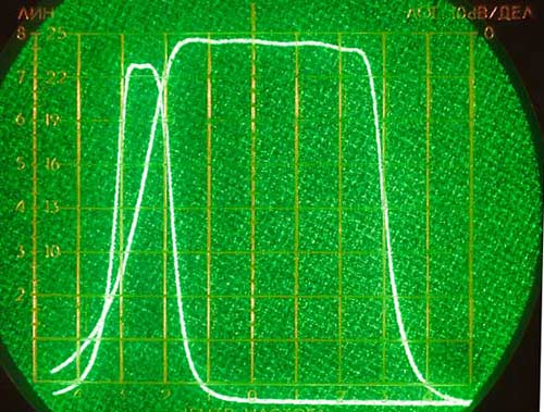
It looks like the linearity of the filters when two test signals are out of the passband is determined by the matching networks inductors. In any case the obtained values satisfy requirements with a good margin. The passband/stopband characteristics of the both filters are shown below.
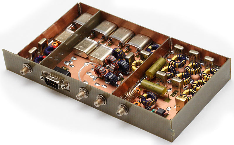
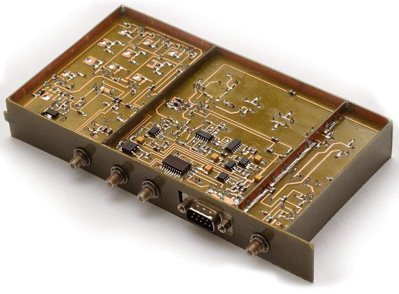
The RF Unit schematics can be downloaded Here are the photos of the RF Unit.
|

All materials provided here are copyright by Oleg Skydan UR3IQO (unless otherwise explicitely specified). In all cases, materials are
provided for the purpose of self education
and training in Amateur Radio. No use may be made for commercial purposes without
permission of the author.
Please send any comments and questions to Oleg Skydan UR3IQO.
This page was last updated on 10.09.2020 06:50