|
||||||||||||||||||
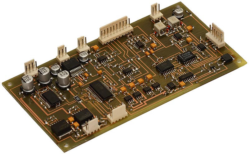
The AF UnitThe AF Unit contains TX circuits - microphone preamplifier, TX audio source switch and gain control, and RX circuits - LPFs, volume control and two power amplifiers - one for the phones and the other for the speakers. The audio RX path linearity is very important to effectively use our ears/brain when chasing for the weak CW signals in the pile up. Another important parameter is the noise level - the noise (either in band or out of band) should be as low as possible. The low noise and hum level in TX audio allows to apply more processing to the signal and low noise RX audio prevents operator from fatigue during the long contests. So the goals were the same as with the Hi-End audio - high linearity and low noise. So the choice to use parts usually found in the Hi-Fi/Hi-End audio equipment is not a surprise. Most part of the signal path is differential to keep low noise and hum, and lower even order distortions. The low noise differential OP amplifiers (OPA1632) are used in LPFs. The high quality volume control ICs (PGA2311/PGA3411) and the Hi-End headphone audio amplifier (TPA6120) provide excellent performance. I used E-MU0202 sound card with the PC FFT spectrum analyser software to measure AF Unit parameters. First of all I tested my sound card (E-MU0202) to determine the limits of my test set.
The Neon's AF Unit were temporary connected to the T03DSP DSP Unit (it uses the same DAC as the Neon - CS4392). A special firmware were loaded to the DSP Unit. It generates two tone signal (for IMD measurements) or single tone one (for harmonics measurements). The AF Unit was tested with the three volume settings - 4Vp-p output voltage, 0.4Vp-p voltage and 0.04Vp-p voltage.
The signal to noise ratio is measured on the following spectrum. The sound card was recalibrated so, that 4Vp-p signal corresponds to -10dB amplitude. The noise voltage at the headphone amplifier output is below 25uV in 10..20000Hz bandwidth. The 50Hz mains spur can also be seen at very respectable -117dB level.
Note: the headphone power amplifier is able to produce 12Vp-p output voltage at maximal power.
I rarely use the speaker, so a simple LM4950 is used to drive the speakers. No attempts were made to measure AF Unit parameters at the speaker output. The TX audio chain is fully differential from the microphone to ADC. The use of differential signal connections with the DSP board solves possible grounding troubles and associated noise. I see no reason to measure the TX audio path. It uses the same parts and principles as the RX one and the linearity/noise requirements are less strict, so it should match them by design.
The schematics can be downloaded
|


All materials provided here are copyright by Oleg Skydan UR3IQO (unless otherwise explicitely specified). In all cases, materials are
provided for the purpose of self education
and training in Amateur Radio. No use may be made for commercial purposes without
permission of the author.
Please send any comments and questions to Oleg Skydan UR3IQO.
This page was last updated on 10.09.2020 06:49