|
||||||||||||||||||||||||||||||||||||||||||||||||||||||||||||
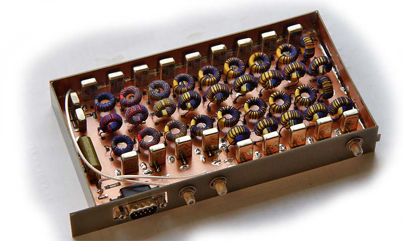
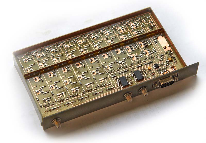
The BPF UnitI tried many different designs before making the final one presented here. The main goals were compact size, low loss, at least 100dB image rejection and IP3>+40dB. The Neon's predecessor T03DSP used the BPF block based on the well known (in exUSSR) design by RA3AO. The design is ultimate in term of IP3 performance. The losses are acceptable, but size and stopband attenuation are far from the Neon's requirements... Martin PA3AKE did an excellent job designing his ultimate BPF block. Unfortunately it is too large to fit into the Neon's cabinet (and remember I need two BPF blocks). On the other hand I do not need IP3=+50dBm and can tolerate 1-2dB higher losses, so I made my own design using the smaller toroids and single board construction. The filters use the same topology as the CDG2000 and PA3AKE BPFs ("shunt C, series trap"). Such filters have much steeper high side slope and provide more attenuation at high side. Since Neon uses near 5MHz IF and high side LO injection, filters properties help to obtain the necessary image suppression.
The BPF filters use T50-2 toroids on 160m and 80m bands, T50-10 on 10m band and T50-6 on the
other bands. The 160m-30m BPFs are 3 stage designs the others are 4 stage ones. The schematics
can be downloaded Table 1. The BPF unit insertion loss
Table 2. The BPF unit IP3 performance
|
All materials provided here are copyright by Oleg Skydan UR3IQO (unless otherwise explicitely specified). In all cases, materials are
provided for the purpose of self education
and training in Amateur Radio. No use may be made for commercial purposes without
permission of the author.
Please send any comments and questions to Oleg Skydan UR3IQO.
This page was last updated on 10.09.2020 06:49

